|
The copyright of all images shown
on this page is owned by M. Feuerbacher.
|
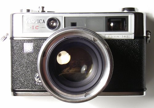
Yashica Lynx 14 E: Light metering problems
by M. Feuerbacher, 2005.
The Yashica Lynx is to my knowledge the only 60's rangefinder which was equipped with a f/1.4 lens. The lens is not only fast but also very sharp (it is definitely comparable to the Leitz Summilux), which makes this model a preferrable low-light camera. My exemplar was in very good shape but there was a problem with the light metering system. If exposure times faster than 1/60 s were chosen, the light meter always showed the "over" sign no matter which aperture is chosen. For all other time / aperture combinations the meter worked fine. This obervation made me feel that there might be a contact problem with the meter sliders so I approached the problem through the front lens barrel.
Please read the instructions completely before you start.
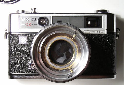
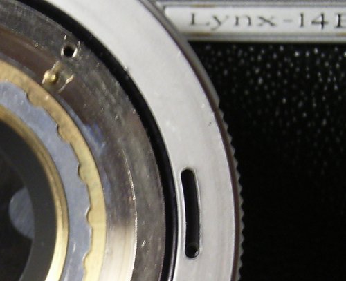
| 1) Remove the name plate. The thread is right handed, as all the following ones. | |
|
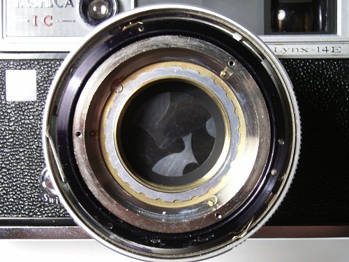
2) Remove the front lens cell using a spanner tool or a caliper gauge. The cell comes of as a whole and you have access to the shutter blades. The aperture is behind the shutter, so if you need to clean them at this stage set the shutter to B and lock it. hree brass screws are visible now. Remove them. Then the filter ring comes off. |
 |
|
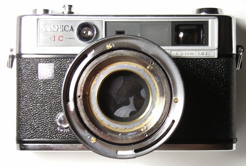
3) The next three brass screws show up. Remove them and the exposure-time ring comes off. |
 |
|
4) Under the exposure-time ring is another ring with two long and three short slits. |
 |
|
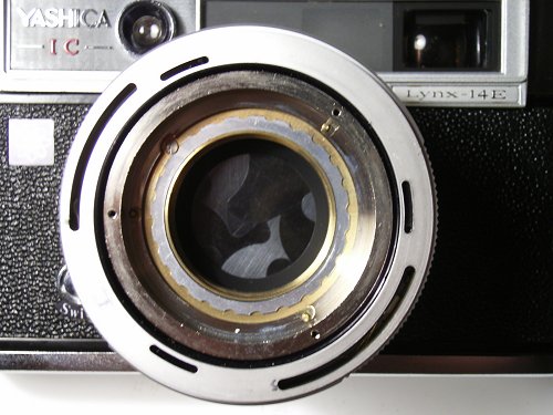
5) The short slits can be used to calibrate the exposure meter. Make sure that you note the position of the screw holes in the slits. This ring can be taken off without removing any further scews. |
 |
|
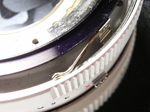
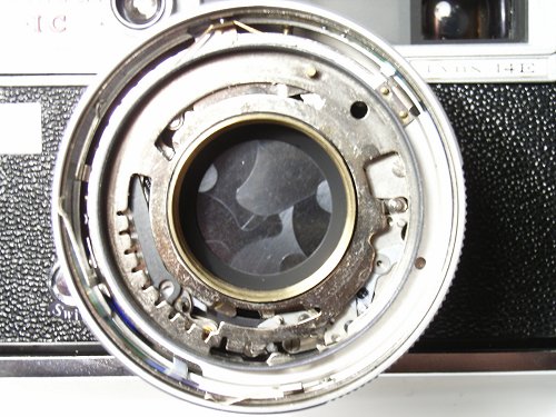
6) You have now access to two sliders (at 9- and 5-o-clock position) which make contact to the inside of the previously removed ring. There is also a copper spring which carries a small ball making the clicks of the ASA selector (11-o-clock position). If you carry on, keep this in mind and make sure that you dont loose the ball or drop it into the camera intereor. |
 |
|
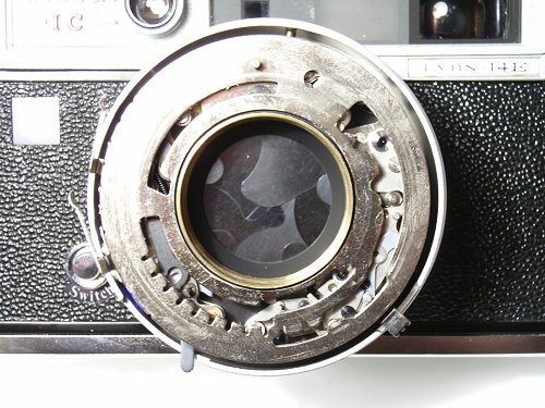
7) The image shows a detailed view of the lower slider |
 |
|
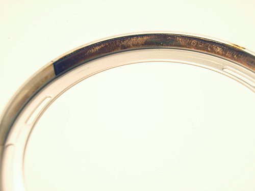
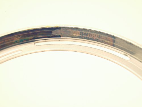
8) The images show the inside of the ring with the slits. A strip of metal is glued on it, with which the sliders make contact. The mechanism for light metering is as follows. One of the sliders is attached to the lens barrel and one to the aperture ring. As you turn the aperture ring, the distance of the sliders on the metal strip changes and so changes the resistance between the sliders. This resistance is used to balance the incident-light dependent resistance given by the meter cell. There are two other sliders for the exposure-time setting. These are visible through the gap between the black ring and the barrel (fig. 8). You can access them from this point but it is not easy to clean them. You can easier clean them by going further. Remove the knurled ring which is locked with the flattened screw. (Turn the screw such that the flat side points towards the inside of the barrel. Then the knurled ring is free and you can turn it). The black ring and the steel part come off as a whole. You have now access to all sliders and to the metal strips making the contacts. Clean all sliders and all metal strips well, using e.g. contact spray. In my case the corrosion of the metal strips caused the problem. It was not possible to bring the camera into proper operation by mere cleaning. I had to replace the ring by another one from a spare camera. I am indebted to Lars Cousineau for providing me with a parts camera where I could take it from. |
  |
|
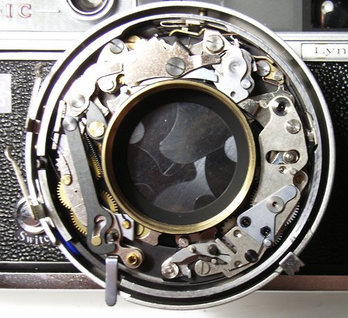
9) After the removal of the black and steel rings you see another ring which contains sliders and corresponding metal surfaces. Remove it and clean it. |
 |
|
10) After removal of the last ring you find the cocking rack. |
 |
|
11) If you remove the cocking rack you have direct access to the shutter. Reassembly is straightforward. Follow these instructions in opposite order. Some remarks:
Once again I thank Lars Cousineau for providing a parts camera from which I could take a vitally important spare part. |
 |