|
The copyright of all images shown
on this page is owned by M. Feuerbacher.
|
by M. Feuerbacher, 2004.
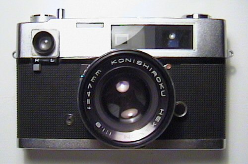
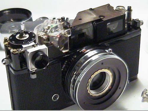
The Konica Auto S was the first rangefinder camera with an auto-exposure feature. Its outer appearance is in some respect resembling the much more widespread Auto S2 but its internal construction is significantly different. My specimen had the following defects:
| Remove the name plate with a friction tool. The front lens cell comes off with the name plate ring. The thread is right handed, as all the following ones. | |
| Remove the built-in shade (3 screws). You find a brass ring locked with a sealed screw. Remove this ring as well. In my specimen, taking off this screw took only one turn. Remove the ring with the exposure-time scale. | 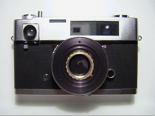 |
| Then you have access to the shutter. Here the cocking rack is still on it. The cocking rack is removed simply by lifting it off. | 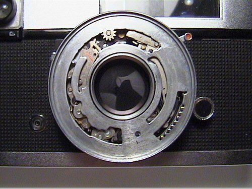 |
| Without the cocking rack. If the shutter is jammed, you now have access to all the gears and to the shutter blades. | 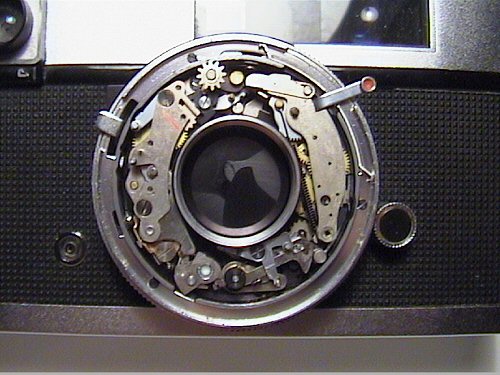 |
|
The aperture blades are behind the shutter. In order to directly access them, you have to go further. Remove the top cap. There are no directly visible screws. One is hidden under the rewind lever and there is another nut under the film-transport lever. |
 |
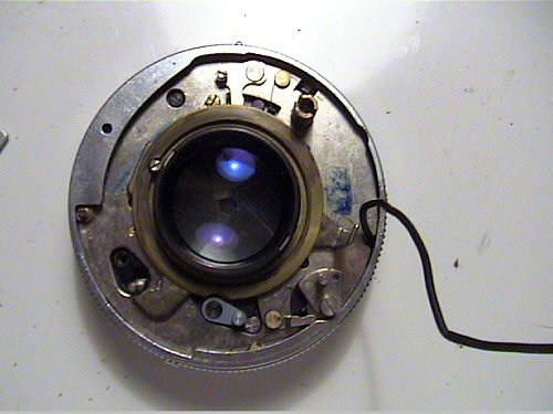
| The camera has an extraordinarily large potentiometer, which, as in the Konica Auto S2, is protected by a transparent plastic cover. | 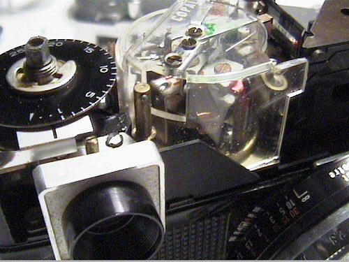 |
|
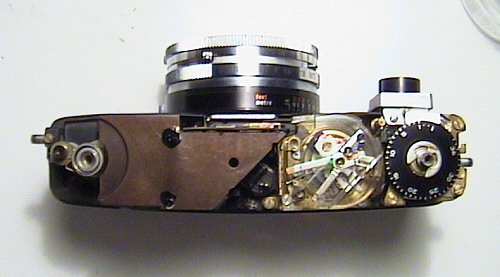
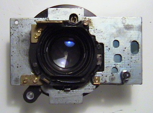
Top view with the top cover removed. In order to remove the lens barrel, remove the bottom plate and the leatherette. Under the leatherette you find 4 screws. Remove them and the barrel comes off. There are no connecting wires.
|
 |
| A view on the body with the lens barrel removed. Above the film-chamber cone you see a, which connects with the socket seen at the top of the next picture. This is the mechanism to transfer the shutter speed to the potentiometer. When you reassemble the camera, you have to make sure that the pin and socket have the correct relative orientations. Since the socket makes 1/4 turn per shutter speed, you can of course manipulate this connection to adjust the light-meter reading. | 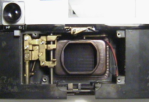 |
|
The lens barrel with the base plate. In order to remove the upper collar, remove the three screws on its side... |
 |
| ... one of which is shown in this picture. Then the collar comes off. | 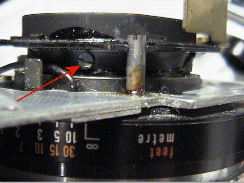 |
| To go furhter, remove the three short and the one long brass screws. For more convenient furhter work, desolder the PC connector cord. | 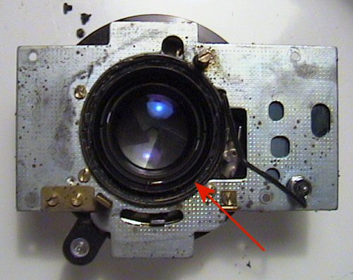 |
| Remove the outer retainer ring (arrow in the previous picture) | 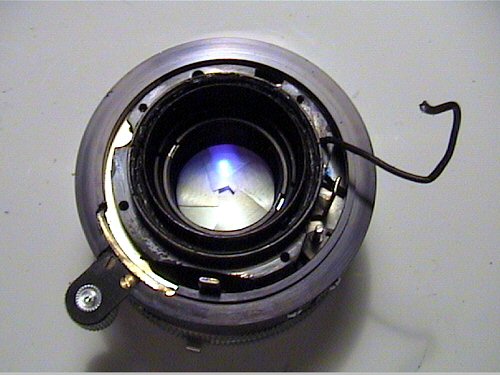 |
|
Finally, you have access to the rear lens group. Remove it with a spanner tool. |
 |
|
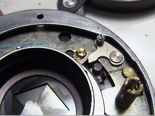
You can clean the aperture blades now. For their front side, set the shutter to B. This image shows the aperture selection mechanism. The blades are moved by displacement of the black spring loaded pin on the right. The wedged cam at the top of the picture pushes the lever connecting to the pin according to the aperture selected.
Reassembly is straightforward. You only have to take care with the mechanical exposure-time transfer mechanism as described above. |
 |