The pinhole camera
by M. Feuerbacher 2003.
Principle, optimum pinhole size
The pinhole camera, which is the prototype of the modern camera,
is a camera obscura with photographic film instead of a viewing screen.
Light enters a dark box through a small aperture, the hole. An image is formed
on the film, the sharpness of which sensitively depends on the size of the aperture
at a given distance to the image plane, i.e. the focal length of the camera.
Numerous different equations for the optimum pinhole size have been published.
Unfortunately, these equations differ by remarkable factors. Sometimes numerical
formulae are given which turn out to be useless, since they are presented without
noting for which unit system (metric, imperial,...) the numerical factors have
been calculated. In the following you find a short derivation of an equation
for the optimum hole size in dependence of the focal length of the camera.
The optimum pinhole size shall be defined as the hole size giving the maximum
resolution. It is determined by two factors:
A) Geometry. Each point of an object to
be imaged should produce as as small as possible point on the film plate. This
can be reached by confining the bundle of light rays coming from an object point
by a small aperture. Thus, for a sharp image, from a purely geometric point
of view, the hole should be as small as possible.
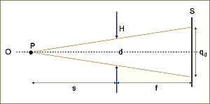
Imagine a point P on the optical axis O at the distance s from the hole of a camera of focal length f. Then
 .
.
Thus the (geometric) size qg of the image of the point object is given by
 .
.
For s>>f (i.e. for most cases) this can be well approximated by
 .
.
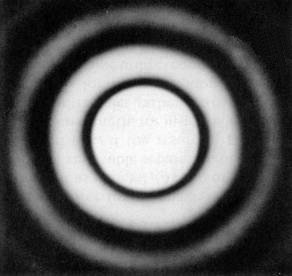
B) Diffraction. On the other hand, if the hole size becomes smaller, diffraction effects increasingly play a role. Diffraction at the small aperture leads to a broadening of each image point, which provides a physical limit of the maximum image sharpness. For a circular hole, the Fraunhofer diffraction pattern (left figure) is given by an Airy function (right figure). Most of the intensity is contained within the central maximum.
 |
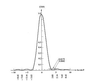 |
The "diameter" qd of the Airy pattern is therefore predominantly determined by the first mimimum of the pattern, which is given by [1]
 ,
,
where lambda is the wavelength of the light used for imaging. This function gives the hole-diameter dependence of the limiting diffraction effect. For the calculation of the optimum hole diameter for the maximum resolving power of the pinhole camera, we therefore have to find the minimum of the function
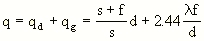
which yields
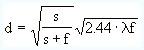 .
.
This equation only differs by a minor numerical factor from
the expression obtained by using the full theory of Fresnel diffraction by L.A.
Turner in 1940 [2].
For s>>f (i.e. for most cases) this can again be well approximated by
 .
.
Inserting a value of 550 nm for the light wavelength, a value which is in the middle of the visible spectrum, we obtain a numerical equation for practical purposes in metric units.
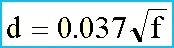 .
.
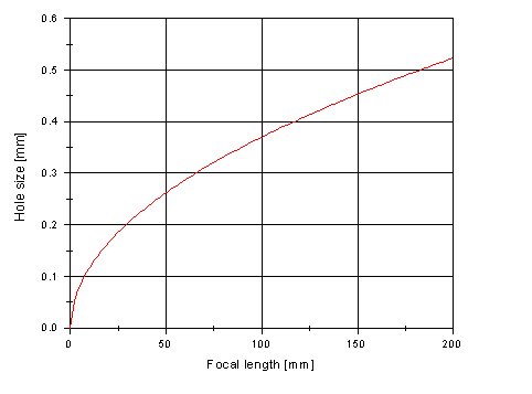
Entering the focal length in millimeters this equation gives you the optimum hole size in millimeters. For your convenience, you find the corresponding graph and a calculator, which you can use for optimum-hole-size determination according to this equation. The calculator additionally gives you the f/number of the camera, which you will need for the exposure-time determination.
Calculator for optimum pinhole size
The exposure time is calculated taking into account two aspects. Firstly, the nominal time according to light metering for the given f/number of the camera is determined. Since, due to the small apertures of a pinholel camera, this usually yields rather long times such as several seconds or even minutes, it is necessary to correct for the Schwarzschild effect.
A) Measurement: Exposure meters do not have f/number scales up to values higher than something like f/32 or so. Correspondingly timescales usually go up to some seconds. Thus, you have to expand your scales into these extreme ranges manually.
A simple solution works like this: Produce two strips (e.g. of paper or cardboard) containing an extension of the f/number and time scales respectively.
f/numbers
|
16
|
22
|
32
|
44
|
64
|
88
|
128
|
176
|
256
|
352
|
512
|
times
|
1/60
|
1/30
|
1/15
|
1/8
|
1/4
|
1/2
|
1
|
2
|
4
|
8
|
16
|
Then do the light metering and place the strips such that corresponding values are adjacent for a reference value at the left end of the scale. As an example, imagine your light metering yields 1/15 sec at f/16. Then place the strips as follows
|
16
|
22
|
32
|
44
|
64
|
88
|
128
|
176
|
256
|
352
|
512
|
||
|
1/60
|
1/30
|
1/15
|
1/8
|
1/4
|
1/2
|
1
|
2
|
4
|
8
|
16
|
You can find appropriate combinations on the right side of the scale. If your camera has a f/number of f/176, then the resulting exposure time is 8 seconds. Most probably, the f/number of your camera is somewhere between the numbers on the scale. Then use the next higher number, except if the number is very close to the next smaller number, which in that case should be used.
Alternatively, you can calculate the exposure time, referring to a reference value which is on the scale of your exposure meter, e.g. f/16. If you use smaller apertures the f/numbers decrease by a factor of Sqrt(2) per step, which leads to an increase of the exposure time by a factor of 2.
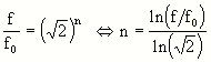
Here, fo is the reference value, e.g. f/16. Thus the exposure time follows
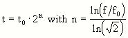
where to is the time corresponding to the reference f/number fo.
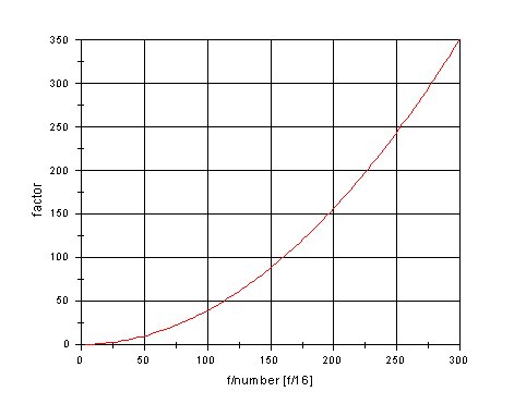
Note that you have to do this calculation just one time for each camera. Once you have calculated 2^n you only have to multiply the measured exposure time at the reference f/# with the constant factor. In the following graph, the factor is given as a function of the f/# of the camera using f/16 as reference value. It thus gives the factors the exposure time measured for f/16 has to be multiplied with.
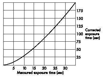
B) Schwarzschild correction: The such determined exposure time, which in the following will be referred to as measured exposure time, has to be corrected by another factor due to reciprocity failure of the film at exposure times above some seconds (Schwarzschild effect). This correction is done via an experimental curve specific for the film used. The curve shown below is the one determined and published by Ilford. It holds for the following film types: HP5, FP4, Delta 100, Delta 400. For other films please refer to the specifications given by the manufacturer.
The criteria for a "good hole" are the following.
(1) The hole should have the right size with respect to the focal length of
the camera and, much less important, to the object distance. This point has
been treated extensively in the first paragraph. (2) The hole should have a
properly circular shape and (3) it should be flat, it should not show a grout
at its edges.
(1) and (2) are highly important factors directly affecting the quality of the image. A hole having frayed edges leads to a strange frayed outer limit of the image. A non-flat hole usually results in a higher effective thickness of the foil used and therefore leads to vignetting of the image. These factors can be accounted for using the right hole-manufacturing technique. Two techniques, wich both, whith some practice and careful work, potentially leading to good results will be described in the following.
A: Making a hole using aluminum foil
This technique will with some practice lead to pleasing results. The drawback is that the holes are very sensitive. You should not touch them and even protect them agains stronger winds. (Even take care if you want to blow dust or dirt away!). The advantage is, that if you take care of the flatness of the edges of the hole, you will not have problems with vignetting. The image field will be large, which is particularly important when using small focal lenghts.
B: Making a hole using a thin metal plate
This technique needs some practice but the result is a very round and flat hole of high stability. The size can be adjusted perfectly.
|
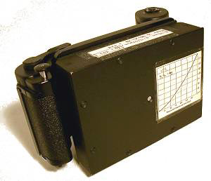
This image shows a partly self made 6 x 9 camera with a very short focal length of 49 mm. The front part is a wooden box with an aluminum front plate, the interior of which is carefully covered with light absorbing felt and matte black paint. It is attached to a mamiya film casette which contains all mechanics. There is no shutter. For pinhole cameras large negative formats should be preferred in order to keep the magnification factors during printing low. On the front you can see the Schwarzschild diagram for my preferred film. I have glued it there to have it always with me. Some other notes (e.g. the correction factor and the f/# value for the camera) which are required for the calculation of the exposure time are seen on the top. |
 |
|
The mamiya film casette. It is not so easy to build a reliable film transport mechanism by yourself, so it is better to resort to commercial solutions. The disadvantage of this particular setup is its weight. Keep in mind, for pinhole photography you usually have to carry a tripod as well. More detailed pictures of the camera can be found here |
 |
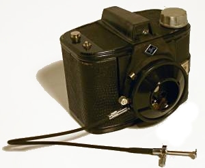 |
This pinhole camera was built on the basis of an Agfa Clack camera (in the US was sold as Agfa Weekender) which you can buy at ebay for next to nothing. It has a 6 x 9 format at a focal length of 79 mm, i.e. slight wide-angle character. The advantage of this solution is that the camera is very light and the shutter mechanism as well as the viewfinder of the clack can be used |
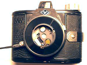 |
I have amputated the lens (and some of its mount) and placed a hole of appropriate size behind the aperture carrier (in order to reduce the focal length somewhat more). This even allows for the use of the built in yellow filter, which can be swept in front of the hole by means of the handle on the right. The shutter mechanism of the Agfa Clack (in contrast to the 6 x 6 model "Click") has a "B" setting and a cable release can be attached, which makes it usable for pinhole photography. More detailed pictures of the camera can be found here |
( Click on the images to see a larger version )
|
Fig. 1: The pinhole was made using Aluminum foil just
by stabbing a hole with a pin. No particular care was taken for making
the hole round or flatten the edges. As you see this leads to a significant
amount of vignetting, and the border of the image is showing the uneven
shape of the hole. |
 |
| Fig. 2: The pinhole used was made from Aluminum foil here as well. However, in this example I took much care of avoiding non flat borders of the hole. As you see there is much less vignetting, but you can still see that the corners are a little darker. The hole size was chosen too small (with respect to the above considerations) by a factor of 2. Thus, diffraction effects come into play and limit the sharpness of the image. |  |
| Fig. 3: The pinhole was made using a thin metal plate and its size was chosen according to the above calculation in this example. There is no vignetting even in the very corners of the negative ( 6 x 7 cm). Furthermore the image is very sharp. Have a look at the signs in the foreground (click the image to see a larger version), you can read part of them! | 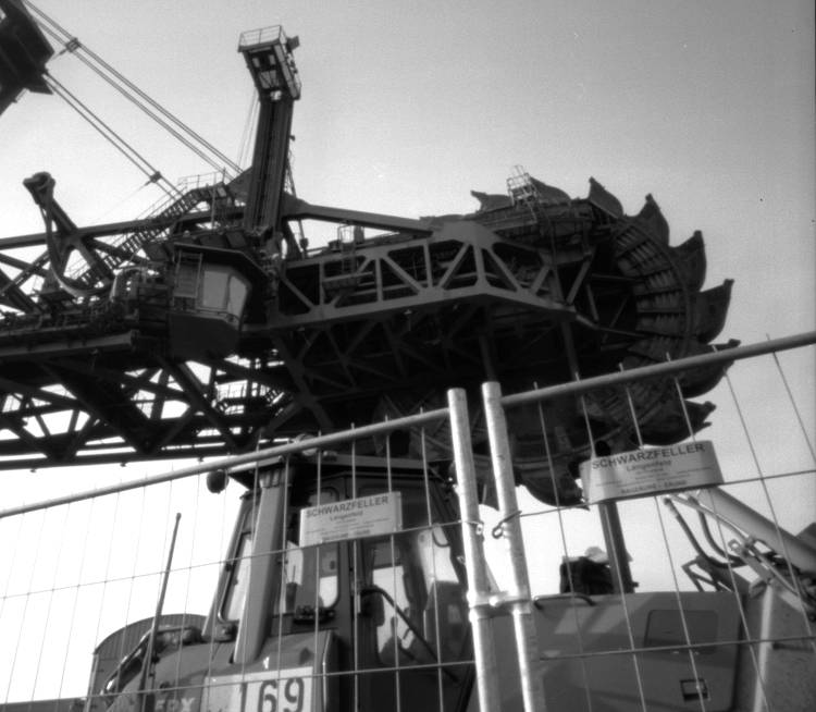 |
[1] E. Hecht and A. Zajac: Optics. Addison Wesley, 1974.
[2] L.A. Turner, Am. J. of Physics 8, 1940, 112.